DAQ Array
3-Channel 40 MSPS USB DAQ with an integrated L1/L5 switchable RF front end
Overview
A high-speed USB data acquisition device with two operating modes. In raw sampling mode, it delivers three synchronized channels at 40 MSPS each. In IQ demodulation mode, it outputs complex baseband I/Q streams centered at 50 MHz with 10 MHz bandwidth — with an integrated L1/L5 switchable RF front end ahead of the converters, so the instrument brings its own band selection rather than depending on anything else in the chain.
Plug-and-play USB connectivity makes it suitable for rapid prototyping, software-defined radio, and laboratory signal analysis without dedicated PCIe hardware.
All three channels are sampled simultaneously with known phase relationships, which is what makes the instrument usable as the digitizer behind multi-antenna array work — coherent processing and direction finding depend on the relative phase between channels being stable and known. The diversity GNSS antenna array is the other multi-antenna project in this section.
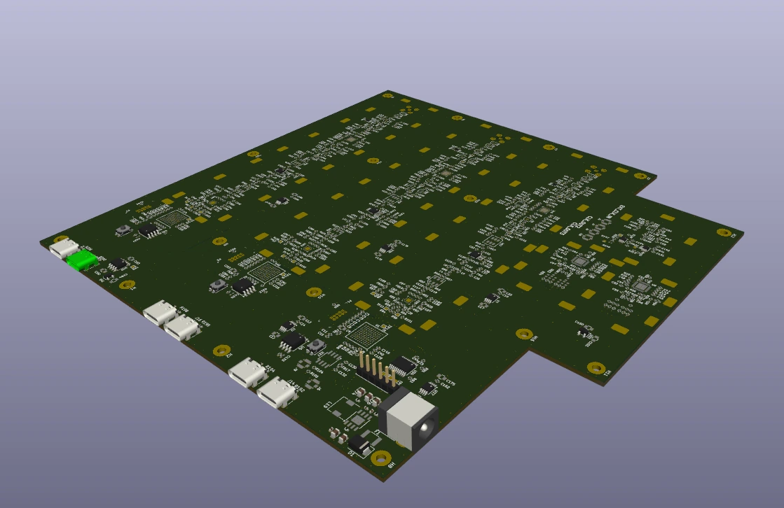
Board Render
Key Specifications
| Parameter | Value |
|---|---|
| Channels | 3 (simultaneous, synchronized) |
| Raw Sampling Rate | 40 MSPS per channel |
| IQ Demodulation | 50 MHz center frequency, 10 MHz bandwidth |
| RF Front End | Integrated L1/L5 switchable front end (current configuration) |
| Interface | USB 3.0 (USB-C) |
| Resolution | High-speed ADC |
| Triggering | Internal and external trigger options |
| Form Factor | Compact enclosure, bus-powered option |
| Variants | Current: DAQ array with the integrated L1/L5 switchable front end — future: DAQ-only variant, [TBD] |
Current configuration and future variant
What is built today is the DAQ array combined with an integrated L1/L5 switchable RF front end — the band switching is part of the instrument. A DAQ-only variant without the RF front end is a future product variant: its scope is [TBD] and it is not available today.
Key Features
- Dual Operating Modes — Switch between 40 MSPS raw sampling and IQ demodulation on the fly
- IQ Demodulation — Complex baseband output centered at 50 MHz with 10 MHz bandwidth, ready for SDR processing
- Integrated L1/L5 RF Front End — Band selection between L1 and L5 is built into the current configuration of the instrument
- Three Synchronized Channels — Sample across all channels simultaneously with known phase relationships
- 40 MSPS Raw Mode — Capture wideband signals and transient events with high temporal resolution
- USB Connectivity — No PCIe slot required, works with laptops and embedded hosts
- Streaming Architecture — Continuous data streaming to host over USB for real-time processing
- Software SDK — Cross-platform API for integration into custom applications
Applications
- Software-defined radio (SDR) — direct I/Q baseband capture through the integrated L1/L5 switchable front end
- Multi-channel signal analysis and recording
- Phased array and direction finding development
- Radar and communications testbed
- Education and research laboratory use
Detailed Specifications (Preliminary)
Values marked [TBD] are unresolved. Rows that carry a figure are the existing published product text, not a measured specification.
Analog Input
| Parameter | Min | Typ | Max | Unit |
|---|---|---|---|---|
| Number of Channels | — | 3 | — | |
| Sample Rate (per channel) | — | 40 | — | MSPS |
| RF Front End | — | Integrated L1/L5 switchable front end (current configuration) | ||
| ADC Resolution | — | [TBD] | — | bits |
| Input Bandwidth | — | [TBD] | — | MHz |
| Input Voltage Range | [TBD] | [TBD] | [TBD] | V |
| Input Impedance | — | [TBD] | — | Ω |
| Input Coupling | — | [TBD] | — | AC / DC |
| SFDR (typical) | — | [TBD] | — | dBc |
| SINAD (typical) | — | [TBD] | — | dB |
| Channel-to-Channel Isolation | — | [TBD] | — | dB |
| Channel Skew | — | [TBD] | — | ps |
IQ Demodulation Mode
| Parameter | Min | Typ | Max | Unit |
|---|---|---|---|---|
| Center Frequency | — | 50 | — | MHz |
| Bandwidth | — | 10 | — | MHz |
| I/Q Sample Rate | — | [TBD] | — | MSPS (complex) |
| I/Q Resolution | — | [TBD] | — | bits per component |
| Image Rejection | — | [TBD] | — | dBc |
| LO Feedthrough | — | [TBD] | — | dBm |
| Quadrature Error | — | [TBD] | — | deg |
| Gain Imbalance (I/Q) | — | [TBD] | — | dB |
| Output Format | Interleaved I/Q ([TBD]) or dual-channel streaming | |||
Open point — sample-rate figures on record
This page carries the published product text: 40 MSPS raw sampling. Project documentation for the associated software receiver also describes the digitizer as 12-bit, 10 MSPS I + 10 MSPS Q per channel. The two figures are not reconciled, so the published figure is shown unchanged and the point is marked [TBD] rather than silently replaced. Treat the sample rate as unconfirmed until the discrepancy is resolved.
Digital / Interface
| Parameter | Value |
|---|---|
| Host Interface | USB 3.0 (USB-C) |
| Maximum Sustained Throughput | [TBD] |
| Data Streaming | Continuous, real-time |
| Trigger Modes | Software, external, internal |
| Onboard Buffer | [TBD] |
| FPGA | [TBD] |
| SDK / API | C / Python ([TBD]) |
| Supported OS | Linux, Windows, macOS |
Mechanical
| Parameter | Value |
|---|---|
| Dimensions | [TBD] |
| Weight | [TBD] |
| Enclosure | [TBD] (e.g., extruded aluminum) |
| Input Connectors | [TBD] (e.g., SMA, BNC) |
| Power | Bus-powered or external [TBD] |
Environmental
| Parameter | Value |
|---|---|
| Operating Temperature | [TBD] |
| Storage Temperature | [TBD] |
| Humidity | [TBD] |
Documentation
The draft product specification collects this page's structure, document control and specification tables into one document. It is stamped as content not final on every page and is not a released specification.
Status
Product in active design phase. Preliminary specifications subject to change; no figure on this page is final.
Inquire about this product →