Diversity GNSS Antenna FPGA
25 fixed L1 beams to 25 GNSS receivers, with an FPGA mux selecting the best position solution
Overview
A 25-element GNSS antenna array operated as a static beam array: the elements form 25 fixed beams of differing pattern coverage, and each beam feeds its own L1 GNSS receiver. An FPGA mux aggregates the 25 receiver streams and selects the best position solution across the array. The beam geometry is fixed by the array itself — the patterns are not shaped, pointed or adapted at run time.
The 25 beams run in parallel: each of the 25 beams has its own receiver producing its own data stream, and the FPGA mux gathers those streams into a single host data path while preserving which stream came from which beam. That correspondence is what makes the array usable at all — a position solution is only worth anything if it can still be attributed to the beam that produced it.
The project is single-band: L1 (1575.42 MHz) only, no second band and no band selection. The selection rule the mux applies across the 25 streams, its update rate and the host interface are [TBD] and are not asserted here.
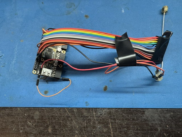
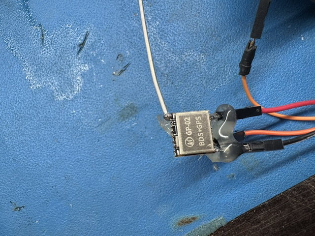
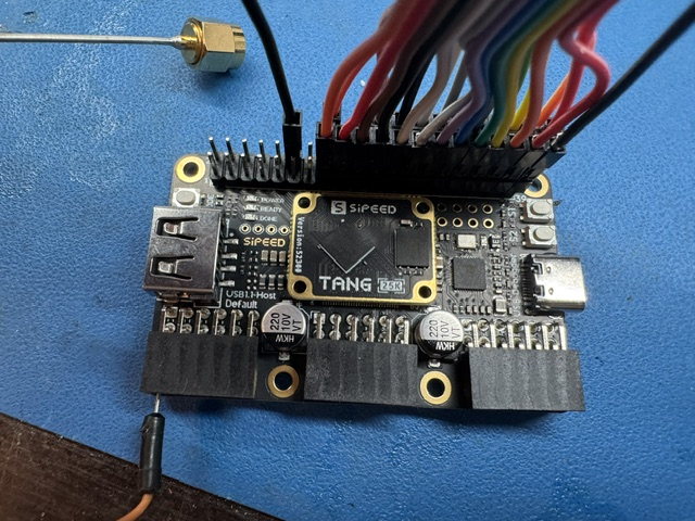
Bench Prototype
Key Specifications
| Parameter | Value |
|---|---|
| Antenna Beams | 25 fixed beams, static geometry (pattern diversity) |
| GNSS Receivers | 25 — one L1 receiver per beam |
| Frequency Bands | L1 (1575.42 MHz) only |
| Bandwidth | Up to 10 MHz |
| Beam Architecture | Fixed beams, static geometry — no adaptive processing |
| Antenna Aggregation | FPGA mux — 25 receiver streams aggregated, best position solution selected |
| Supported Signals | GPS L1 C/A; Galileo E1; BeiDou B1 |
Key Features
- 25 Fixed Beams — 25 antenna elements form 25 beams whose coverage is set by the array geometry and does not change at run time
- 25 L1 Receivers — One GNSS receiver per beam, so every beam produces its own position solution
- FPGA Mux — The 25 receiver streams are aggregated, and the best position solution across the 25 beams is selected from them
- Single-Band Simplicity — L1 only (1575.42 MHz); no second-band hardware and no band switching
- Compact Form Factor — Designed for integration into UAVs, ground vehicles, and fixed installations
Applications
- High-integrity GNSS receivers for critical infrastructure and autonomous systems
- High-integrity positioning for autonomous vehicles
- GNSS signal monitoring and spectrum analysis
- Research and development for advanced navigation systems
Detailed Specifications (Preliminary)
Values marked [TBD] are unresolved. Board-level and part-level detail is deliberately not stated — no FPGA part, receiver part, antenna part, pinout or clock plan is asserted on this page.
RF / Electrical
| Parameter | Min | Typ | Max | Unit |
|---|---|---|---|---|
| RF Input Frequency (L1) | — | 1575.42 | — | MHz |
| Instantaneous Bandwidth | — | 10 | [TBD] | MHz |
| Number of RF Channels | — | 25 | — | |
| Noise Figure | — | [TBD] | — | dB |
| Gain | — | [TBD] | — | dB |
| Phase Noise @ 10 kHz | — | [TBD] | — | dBc/Hz |
| ADC Resolution | — | [TBD] | — | bits |
| Input IP3 | — | [TBD] | — | dBm |
| Channel-to-Channel Phase Stability | — | [TBD] | — | deg |
| Power Supply | [TBD] | [TBD] | [TBD] | V DC |
| Power Consumption | — | [TBD] | — | W |
Digital / Processing
| Parameter | Value |
|---|---|
| Beam Mux | FPGA-based ([TBD] part) |
| Front-End Multiplexing | 25 L1 receiver streams aggregated by the FPGA mux |
| Position Selection | Best position solution across the 25 beams ([TBD] rule) |
| Host Interface | [TBD] (USB / Ethernet / PCIe) |
| Data Output Format | [TBD] |
| Update Rate | [TBD] |
| Onboard Storage | [TBD] |
Mechanical
| Parameter | Value |
|---|---|
| Dimensions | [TBD] |
| Weight | [TBD] |
| Enclosure | [TBD] (e.g., milled aluminum, shielded) |
| Antenna Connectors | [TBD] (e.g., SMA, MMCX) |
| Mounting | [TBD] |
Environmental
| Parameter | Value |
|---|---|
| Operating Temperature | [TBD] |
| Storage Temperature | [TBD] |
| Vibration / Shock | [TBD] |
| Ingress Protection | [TBD] (IP rating) |
Documentation
The draft product specification collects this page's structure, document control and specification tables into one document. It is stamped as content not final on every page and is not a released specification.
Status
Product in active design phase. Preliminary specifications subject to change; no figure on this page is final.
Inquire about this product →